Design Your Own Graphic Equalizer
Understanding Noise In Circuits

PLEASE follow the directions. I am not responsible if you screw this up and Baal or some other demon sucks you into the pits of Hell
You First need to build the circuit below and connect it to Line-in of Sound Card:
Then use this software to see the wave forms
Previous Posts
- How To Build A Gauss Rifle
- Build Your Own Time Fountain
- Make A High Resistance Meter
- Build A DC Solid State Relay
- Build A Dual Power Supply
- High-Speed Data Switch
- Making Your Own Battery Backup
- Building A Phase Lock Loop
- Build A Battery Level Indicator
- Voltage Level Indicator
Archives

Links

Building A Phase Lock Loop
Build A Battery Level Indicator
Voltage Level Indicator
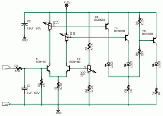
 This discrete circuit is derived from a Siemens Application Note 1974. This circuit uses common components of today. The circuit is here as it is of high educational value. I have not tested it. You can 'simulate and test' or 'wire it up and try' and let me know how it worked. The Circuit is also a simple analog to digital converter. You can use optos in place of LEDs. T1 and T2 make a differential amplifier. T3, T4 and T5 driving the LEDs are comparators. Now to learn more on how they work you have to study circuits at 4QD-TEC and search Educypedia for more. Some pspice ideas here and at 101Science.com. When input voltage is increased T1 is turned on which leads to more base current for T3 which Lights LED1. When input voltage is less T2 turns on as it gets a better base current from P3 which turns on LED2 via T4. When both LEDs are off T5 gets biased as no drop across R5 which lights the LED3 thru T5 hopefully. What you need to know is a small current Ib thru the base-emitter path in the direction of the emitter arrow will lead to a large Current Ic thru the emitter-collector path in direction of arrow. Ic = B * Ib where B - beta is the DC current gain, it could be 100-400 see Towers International Transistor Selector see chipdir. Beta is different in each transistor you buy and varies with the test conditions and even with temperature and age. The LED1 and LED2 will indicate above or below Limits set by P2 and P1. The Limit Threshold itself is set at P3 i think. LED3 will light when Hi LED and Lo LED both are off. The applications of this circuit are FM tuning indicator, Stereo Balance Indicator (Wire T2 like T1 then we get two channel inputs) and battery level indicator. |


